A Comprehensive Overview of Deep Well Submersible Pump Mechanisms

Table of Contents
1. Introduction to Deep Well Submersible Pumps
2. Understanding Submersible Pumps
3. Types of Deep Well Submersible Pumps
4. Key Components of Deep Well Submersible Pumps
5. Working Principle of Deep Well Submersible Pumps
6. Advantages of Using Deep Well Submersible Pumps
7. Applications of Deep Well Submersible Pumps
8. Maintenance Tips for Deep Well Submersible Pumps
9. Common Issues and Troubleshooting
10. Conclusion
11. FAQs
1. Introduction to Deep Well Submersible Pumps
Deep well submersible pumps are crucial components in various applications, particularly in agriculture, municipal water supply, and industrial processes. These pumps are designed to function underwater, making them highly efficient for extracting water from deep aquifers. This article delves into the mechanisms, types, components, and applications of these vital devices, offering insights into how they operate, their benefits, and maintenance considerations.
2. Understanding Submersible Pumps
Submersible pumps are specialized devices that operate submerged in the fluid they are pumping. Unlike standard pumps that require a suction mechanism, submersible pumps push fluid to the surface, eliminating the need for priming and reducing the risk of cavitation. Their design allows for efficient water movement from deep wells, making them indispensable in numerous sectors.
2.1 Key Features of Submersible Pumps
- Efficiency: Submersible pumps are designed to deliver high efficiency in water extraction.
- Durability: Constructed from robust materials, these pumps withstand harsh conditions.
Space-Saving Design: Their compact construction allows installation in narrow or limited spaces.
3. Types of Deep Well Submersible Pumps
Deep well submersible pumps can be categorized based on various factors, including design, application, and operation. The following are the primary types:
3.1 Vertical Turbine Pumps
Vertical turbine pumps consist of multiple impellers stacked vertically. They are suitable for deep wells and can handle large volumes of water efficiently.
3.2 Borehole Pumps
Borehole pumps are specifically designed for deep wells. They are typically smaller in diameter, making them ideal for narrow boreholes.
3.3 Multistage Pumps
Multistage submersible pumps utilize multiple impellers to increase pressure, making them suitable for applications requiring high discharge pressures.
4. Key Components of Deep Well Submersible Pumps
Understanding the components of deep well submersible pumps is essential for comprehending their operational efficiency. Key components include:
4.1 Motor
The motor powers the pump and is typically sealed to prevent water ingress. These motors are designed for high torque and efficiency.
4.2 Impellers
Impellers are vital in creating flow and pressure. The design and material of the impellers affect performance and durability.
4.3 Diffusers
Diffusers control the flow of water and help convert kinetic energy from the impellers into pressure.
4.4 Shaft
The shaft connects the motor to the impellers, transmitting power necessary for operation.
4.5 Bearings
Bearings support the shaft, ensuring smooth rotation and minimizing friction. They are crucial for longevity and efficiency.
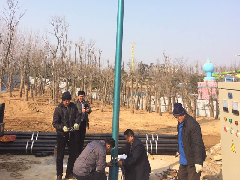
5. Working Principle of Deep Well Submersible Pumps
Deep well submersible pumps operate on a straightforward principle. The motor, located at the bottom of the pump, drives the impellers, which draw water into the pump. As the impellers rotate, they push the water through the diffusers, increasing its pressure. The pressurized water is then forced up through the discharge pipe to the surface.
The unique design of these pumps allows them to function effectively even in deep wells where atmospheric pressure might limit the performance of surface pumps.
6. Advantages of Using Deep Well Submersible Pumps
Utilizing deep well submersible pumps offers several advantages:
6.1 Enhanced Efficiency
Submersible pumps are inherently more efficient than surface pumps due to their design, which eliminates air entrapment and cavitation.
6.2 Space-Saving
Their compact design allows for installation in limited spaces, making them ideal for various applications.
6.3 Reduced Noise Levels
Operating underwater significantly reduces noise, making them suitable for residential areas.
6.4 Longer Lifespan
Due to their robust construction and sealed motor design, these pumps often have a longer operational lifespan compared to conventional pumps.
7. Applications of Deep Well Submersible Pumps
Deep well submersible pumps find applications in various sectors, including:
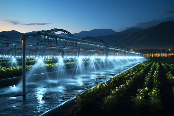
7.1 Agricultural Irrigation
Farmers utilize these pumps to extract groundwater for irrigation purposes, ensuring efficient water supply to crops.
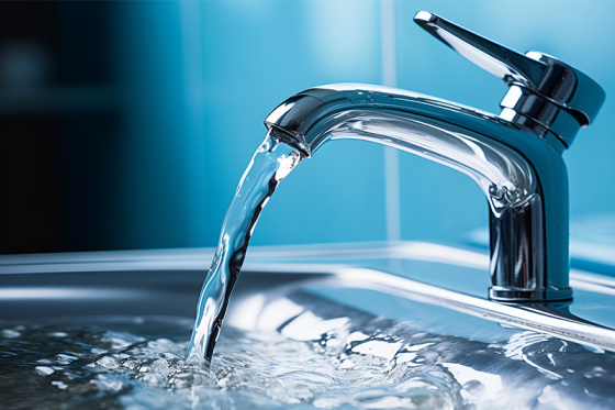
7.2 Municipal Water Supply
Cities employ deep well submersible pumps for public water supply systems, ensuring a constant flow of clean water.
7.3 Industrial Processes
Industries rely on submersible pumps for cooling, process water, and wastewater management.
8. Maintenance Tips for Deep Well Submersible Pumps
To ensure the longevity and efficiency of deep well submersible pumps, regular maintenance is critical. Here are some maintenance tips:
8.1 Regular Inspections
Conduct periodic inspections to check for wear and tear on components, especially impellers and bearings.
8.2 Monitor Performance
Keep an eye on the pump's performance metrics, including flow rate and pressure, to identify any deviations that might indicate issues.
8.3 Check Electrical Connections
Ensure that all electrical connections are secure and free from corrosion to prevent any operational failures.
8.4 Cleanliness
Maintain cleanliness around the pump area to prevent debris from entering the system, which can cause blockages and damage.
9. Common Issues and Troubleshooting
Understanding potential issues with deep well submersible pumps can help in timely troubleshooting. Some common problems include:
9.1 Loss of Prime
If the pump loses prime, it may be due to air leaks or a blocked intake. Checking seals and cleaning the intake can resolve this issue.
9.2 Overheating
Overheating can occur due to a malfunctioning motor or insufficient cooling. Ensure proper ventilation and motor functionality.
9.3 Vibrations
Excessive vibrations may indicate misalignment or wear. Regularly check and align the pump components to minimize vibrations.
10. Conclusion
Deep well submersible pumps play a pivotal role in water extraction across various industries. Their efficient design, combined with advanced technology, enables them to operate effectively in challenging conditions. Understanding their mechanisms, components, and maintenance requirements is essential for ensuring optimal performance and longevity. With proper care, these pumps can continue to serve essential functions for years to come.
11. FAQs
What is a deep well submersible pump?
A deep well submersible pump is a type of pump designed to be submerged in water, which efficiently extracts groundwater from deep wells.
How does a submersible pump work?
The pump's motor drives the impellers, which push water through diffusers, creating pressure that forces water to the surface.
What are the main advantages of submersible pumps?
Submersible pumps are efficient, space-saving, quieter, and generally have a longer lifespan compared to surface pumps.
What maintenance is required for deep well submersible pumps?
Regular inspections, monitoring performance, checking electrical connections, and maintaining cleanliness are essential for effective maintenance.
Can I use a submersible pump for irrigation?
Yes, deep well submersible pumps are commonly used for agricultural irrigation due to their ability to draw water from deep aquifers efficiently.